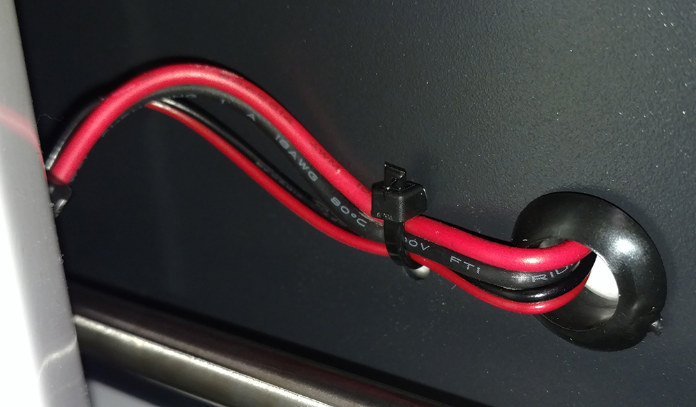
Recently I acquired a Monoprice Select Mini v2 3D Printer and I’ve been having a great time learning and experimenting with 3D Printing on it. It’s a wonderful little printer that is inexpensive (At around $220), puts out great quality prints, it’s easy to work with and to work on. That said, it has a fatal flaw in its design: The wiring for the bed heater and thermistor is routed along a horrible path that lets the wires rub against the gears moving the bed, and these two pairs of wires are zip tied in a place that makes them kink as the bed moves. Between these two problems, the wiring is prone to short, fray, or break entirely. Unsurprisingly, I had to repair mine, read on to find how how.
A visit to the Monoprice Select Mini Facebook
group or the
subreddit shows a surprising (to
me, at least) number of people with related problems.A common chorus when
discussing the printer is “rewire the bed before you do anything else”. It can
manifest as the bed heater not working or the bed temperature readout being
incorrect, typically reading 999 or 0.
Since mine had been OK, and I’d owned it less than a month, I figured I had time. I was wrong. After a couple weeks and a non-trivial number of printing hours, the bed wouldn’t preheat. The temperature readout was OK, but it read about room temperature and didn’t move. I canceled the print, went into the printer’s monitor screen and had it preheat the bed. Still nothing. I knew the wires could be the problem so I moved the bed back and forth to see if it would kick in, and it did when I moved it all the way forward. Move the bed back and it stopped. Classic short behavior, so I knew what I was in for. Now I had two choices: One: Send the printer back and get it fixed or repaired, or two: Fix it myself. Option one meant I’d be without the printer for probably a week or two and when it came back it would still have a bad wiring job. Option two means I could have it up and running in a couple days at most, and I could use a better wiring path that wouldn’t be prone to breaking. I opted to fix it myself, but I didn’t have all the parts on hand which is why it took a couple days to fix. While waiting for the parts to arrive I watched some videos on youtube by others who made similar repairs, but I did not want to drill through the case, so I also researched some other options. Once it all arrived it was actually a very straightforward fix, so I documented it all and here it is!
Requirements
I chose to do a no-drill method using a printed side panel to reroute the wires. I do not want to have to deal with the mess of metal shavings that drilling would cause. The directions below assume this method, plus also rewiring the heater connection. Here are the parts I printed to replace the side panel and help run the wires:
- Back panel: https://www.thingiverse.com/thing:2451362
- Front panel: https://www.thingiverse.com/thing:2370329
- Cable brace: https://www.thingiverse.com/thing:1937513 – I used the second version, and mirrored it in Cura so the hole was on the correct side for the side mount cable path
Tools
You’ll need these tools to either reroute the wiring or to repair the bed wires
- Cutters for wire and zip ties
- Philips head screwdriver
- Pliers
If you need to repair the bed wires, you will also need these:
- Wire stripper
- Helping Hand or similar clamp/stand to hold parts in place while soldering
- Multimeter
- Soldering iron
- Soldering tip cleaning sponge (brass or other)
- OR: Instead of all that, you can buy a new bed+wires
Supplies
If you are only rerouting the wires, you’ll want to grab…
- Braided cable sleeve, spiral tube wrap, or similar
- Small zip ties
If you are repairing the bed wires, you’ll also need…
- Solder - Preferably rosin core tin/lead blend for wire/electronics
- 18AWG flexible silicone wire - For the heater wires, if you have to replace the thermistor wires you can use some smaller gauge wire like speaker wire
- Kapton tape - The old tape may be resuable but it’s not worth the hassle
- Heat shrink tubing - 3.5mm diameter should be OK
Rewire Part 1
Getting the wires out
- Use the Move menu to raise the Z axis a few inches up to have clearance to remove the bed
- Remove side panel where SD socket and USB connector are, the wires plug in just behind here.
- Cut the zip ties along the bed wires inside and outside the unit, you might have to remove the bottom panel for easier access, if so, lay the printer down on its side with the removed side panel end facing up.
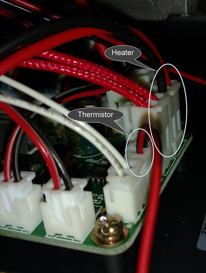
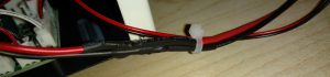
 Identify the bed wires: there are two pairs of wires, a thicker pair for the
bed heater, and a thinner pair for the bed thermistor. Follow them and locate
where they run and where they are plugged into the controller board. The
heater wires have a larger white connector on the board, the thermistor is a
smaller white connector near the open side panel.
Identify the bed wires: there are two pairs of wires, a thicker pair for the
bed heater, and a thinner pair for the bed thermistor. Follow them and locate
where they run and where they are plugged into the controller board. The
heater wires have a larger white connector on the board, the thermistor is a
smaller white connector near the open side panel.- Mark and/or snap a photo of the connectors so you know which side is red and which is black, and where they plug in
- Disconnect the bed wires from inside the unit
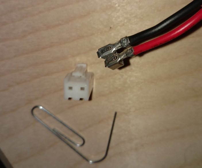
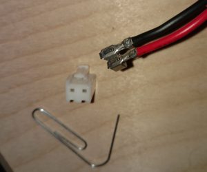 Carefully remove the connector from the end of the heater wires (thicker
wires, larger connector) so the wires can be backed out through the grommets.
You may not need to do this depending on whether or not you can wiggle the
connector through. It is much easier to move the wire without the lump of a
connector on it, and it’s not hard to remove the connector, only need
something with a fine point to push in the little catch on each wire, like a
pin, paperclip, or sharp tweezers.
Carefully remove the connector from the end of the heater wires (thicker
wires, larger connector) so the wires can be backed out through the grommets.
You may not need to do this depending on whether or not you can wiggle the
connector through. It is much easier to move the wire without the lump of a
connector on it, and it’s not hard to remove the connector, only need
something with a fine point to push in the little catch on each wire, like a
pin, paperclip, or sharp tweezers.- Move the wiring back through the grommets so it comes right off the back of the heated bed and not through the body of the printer or the carriage
If you do not need to repair the wires, skip ahead to Rewire part 2.
Repair the wires
- Carefully back out all of the bed leveling screws and set the screws, caps, and springs aside. Don’t lose any pieces!
- At this point the bed is completely separated from the printer so it can be moved it to a better work area, I reattached the connector to the heater wires to keep them together but it will need to be off later to go through the cable sleeve, so it’s up to you.
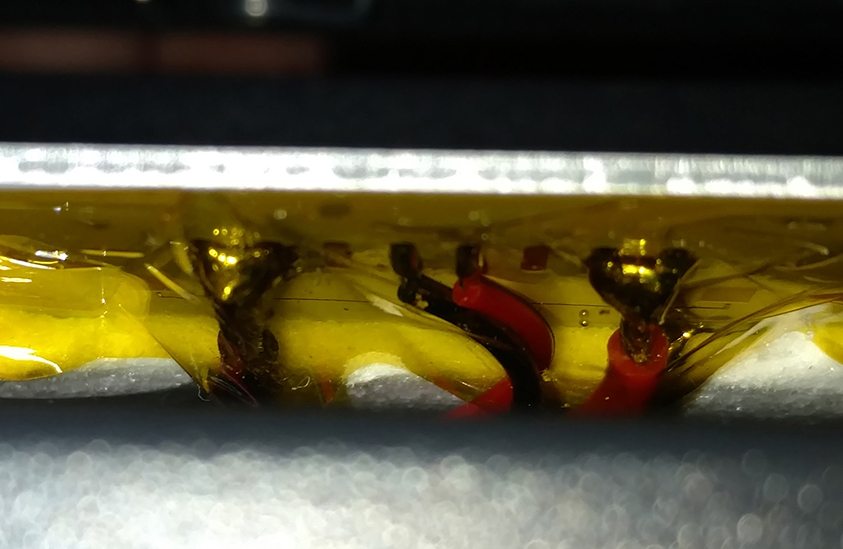
- Using a multimeter I confirmed my red heater wire had a nasty short. The black wire was fine, but I replaced them both anyhow.
- Mark which connection is positive and which is negative on the bed, and/or take a picture for reference
- Remove the Kapton tape covering the solder connections on the bed
- Carefully desolder the thick heater wires from the bed (outer wires): Hold the soldering iron tip on the solder bead until it reflows and then they come right off
- Cut the connector end of the wires off, keeping a few inches of old wire to splice into later so you can reuse the connector
- Cut two lengths of new 18AWG silicone flexible wire: One red, one black, really the color isn’t important, but it’s good to match.
- Strip a bit off both ends of the new wire and the salvaged connector wires
- Solder one end of each new wire to the bed in the appropriate spot
 Put some 1” Kapton tape back over the solder connections. Preferably use new
Kapton tape, not old, but the old may be tacky enough to reuse.
Put some 1” Kapton tape back over the solder connections. Preferably use new
Kapton tape, not old, but the old may be tacky enough to reuse.- Put some heat shrink tubing around the wire to be used after splicing
- Mesh or twist the new and salvaged wire ends together
- Solder each pair of wires together to form a strong bond
- Move the heat shrink tubing so it completely covers the solder on each wire with room to spare
 Melt the heat shrink tubing using a high heat source. I used a heat gun, but a
lighter or torch works
Melt the heat shrink tubing using a high heat source. I used a heat gun, but a
lighter or torch works- If you need to replace the thermistor wires, repeat this procedure again for those, but with appropriate AWG replacement wire
- Replace the bed, using the screws, springs, and caps to reattach it
- You will definitely need to relevel the bed after, but don’t do that yet

Rewire Part 2
Better than new
- Run the bed wires through the hole in the cable brace
- Attach the cable brace on the back of the bed carriage. It needs screws, I used some old PC case screws that fit.
- Slide the wire through some sort of conduit – braided cable sleeve, spiral tube wrap, cable chain, etc. The connector on the heater wires will probably need to be off for it to fit, unless you use spiral wrap which can fit around anything.
- Put a zip tie at either end of the conduit, for example I used braided cable sleeve so I put a zip tie between the bed and the cable brace, and another just before the connectors
- Put the heater wire connector back on if it was removed, and reconnect the heater and thermistor to the main controller board
- Put on the new side panels – If you couldn’t print new side panels because you need the heated bed, just leave the side panel off while you print replacements!
- Relevel the bed and try preheating it
For me, the bed heated right up to 60C where I wanted it, and my prints are back to sticking like I’m used to!

If you choose to do a method involving drilling or if you choose a different side panel configuration, the last few steps may need to change to route the cables through whatever new path is available.